DIY QubIDE Parts list
-
Derek_Stewart
- Font of All Knowledge
- Posts: 3975
- Joined: Mon Dec 20, 2010 11:40 am
- Location: Sunny Runcorn, Cheshire, UK
Re: DIY QubIDE Parts list
What address is the Qubide rom at?
Try setting the jumpers so the the Qubide Rom is in the Rom Port at 0C00H
The Rom should be listed on the startup screen, and it starts the IDE Drive scan.
You may want to fit the Ram and Gal, as the QL with 128K will not be able run a hard drive very well.
Try setting the jumpers so the the Qubide Rom is in the Rom Port at 0C00H
The Rom should be listed on the startup screen, and it starts the IDE Drive scan.
You may want to fit the Ram and Gal, as the QL with 128K will not be able run a hard drive very well.
Regards,
Derek
Derek
Re: DIY QubIDE Parts list
I've tried jumpers in various positions as follows
04000h : I I I I Unusable, ROM - Get Black Screen No Boot
0C000h : : I I I - Get STD Boot screen
20000h I I I : I Unusable, Screen 0 - Get Black and white stripes top half
24000h : I I : I Unusable, Screen 0 - Get Black and white stripes bottom half
C0000h I I I I : - Get STD Boot
C4000h*** : I I I : - Get STD Boot
E0000h*** I I I : : - Get STD Boot
All with no messages to say the card is recognised
Re: DIY QubIDE Parts list
I've tried v1.56 rom and GALS (both Qdegal1,2, qideg1,2) and Qubclone 3.1 rom and gals
For memory GAL only have RAM 512 mcleod and tcat. Memory not recognised for both
For memory GAL only have RAM 512 mcleod and tcat. Memory not recognised for both
Re: DIY QubIDE Parts list
I think you have soldered the resistor network RN1 the wrong way
The dot must be at the other end
resistors have no polarity but bussed resistor arrays have because of the common pin.
The dot must be at the other end
resistors have no polarity but bussed resistor arrays have because of the common pin.
Leon
Projects: https://hackaday.io/projects/hacker/357657
Projects: https://hackaday.io/projects/hacker/357657

Re: DIY QubIDE Parts list
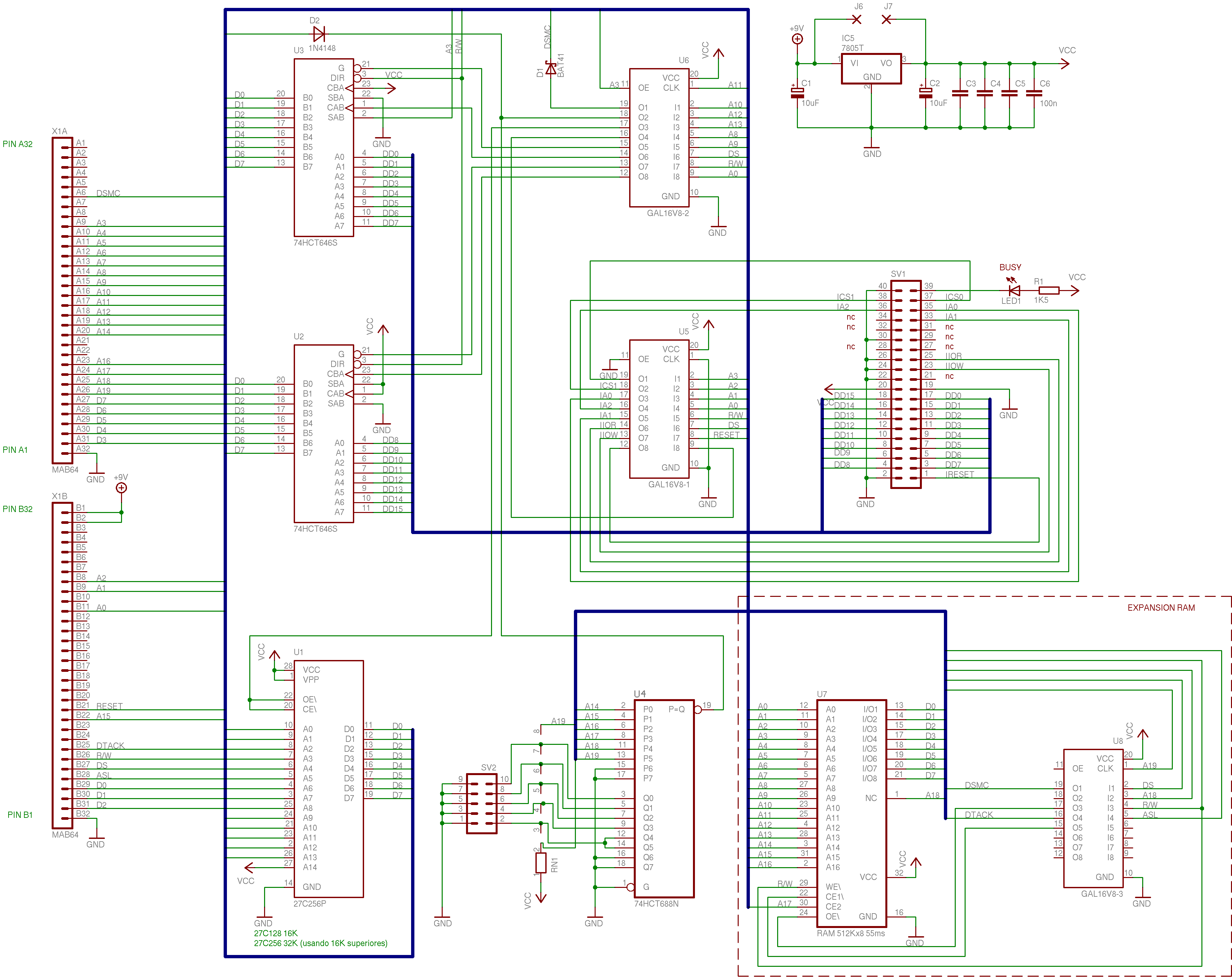
It sound like the rom is not getting decoded - which is the job of the GAL 168V2 in the diagram - also keep in mind the circuit specifies a 32K eprom and ties A14 on this ROM to VCC - this means you must replicate the 16K contents in the ROM so that both the lower and upper have the same contents or just program the upper half of the ROM chip - as the ROM image is 16K but the chip is 32K - it could be some thing as simple as this...
https://hardware.speccy.org/temp/qubide ... squema.png
https://hardware.speccy.org/temp/qubide ... squema.png

Re: DIY QubIDE Parts list
Well spotted! Indeed the array needs to go in the other way round.
ʎɐqǝ ɯoɹɟ ǝq oʇ ƃuᴉoƃ ʇou sᴉ pɹɐoqʎǝʞ ʇxǝu ʎɯ 'ɹɐǝp ɥO
-
Derek_Stewart
- Font of All Knowledge
- Posts: 3975
- Joined: Mon Dec 20, 2010 11:40 am
- Location: Sunny Runcorn, Cheshire, UK
Re: DIY QubIDE Parts list
Hi
I have a Tetroid Qubide kit that needs soldering up, I will see if the GALs can be copied.
You will need different GALs for Qubide v1.56 and v2.xx
I should have both.
I will post them here.
I have a Tetroid Qubide kit that needs soldering up, I will see if the GALs can be copied.
You will need different GALs for Qubide v1.56 and v2.xx
I should have both.
I will post them here.
Regards,
Derek
Derek
Re: DIY QubIDE Parts list
GALS, part list and ROM in attacment.
ROM pins 28 and 1 - Vcc
What ROM chip you have ?
For 27C256 you need to use the second half of the ROM chip ( $4000 - $7FFF )
For 27C512 you need to use the last quarter of the ROM chip ( $C000 - $FFFF ).
ROM pins 28 and 1 - Vcc
What ROM chip you have ?
For 27C256 you need to use the second half of the ROM chip ( $4000 - $7FFF )
For 27C512 you need to use the last quarter of the ROM chip ( $C000 - $FFFF ).
- Attachments
-
- QUBIDE.zip
- (206.78 KiB) Downloaded 37 times
I still have my QL items still available, anyone interested, please contact me at tetroid@inbox.ru