Page 1 of 6
DIY QubIDE Parts list
Posted: Sun Jun 23, 2019 11:14 pm
by axeman
Hi,
I'm just getting the parts together for a diy QubIDE build. Can anyone provide the parts list from the Sellmyretro QubIde kit as I've sourced the same board. I've looked on
http://hardware.speccy.org/temp/qubide-i.html but the resistor array size is ambiguous as is some of the capacitor and other resistor sizes.
Thanks
Tom
Re: DIY QubIDE Parts list
Posted: Mon Jun 24, 2019 1:55 am
by Dave
D1 is a BAT41
D2 is a 1N4148
Caps C3-C6 are 100nF, standard bead type
Two electrolytics by the 7805 are 10uF 2.54mm (.1") radial, 16v
RN1 is a bussed .1" SIL, 8 pin (7 resistors commoned together to the 8th pin) and provides a weak pull down. 3K3 sounds good.
3x GAL16V8 are DIP-20.
1x 74HCT688 is DIP-20
2x 74HCT646 are SOIC-24
The 512Kx8 SRAM is AS6C4008, though there are many pin compatible equivalents.
Re: DIY QubIDE Parts list
Posted: Mon Jun 24, 2019 1:57 pm
by axeman
Brilliant! thanks Dave.
Can't wait to get his built.
Re: DIY QubIDE Parts list
Posted: Sat Oct 05, 2019 7:25 pm
by axeman
Finally got my DIY QubIDE built however all I get is horizontal black and white bars on boot. QL is stock with no other cards. I've prog'd the Eprom with version 1.56A and removed the ram and 3rd gal to simplify. Also realised that you have to program the gal chips but not sure if I have the correct versions, sourced them from here
http://www.retrocomputing.net/parts/sin ... s/docs.htm.
Anyone got any ideas?
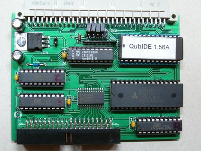
My qubide exactly matches this

- Qubide with 512k RAM
Re: DIY QubIDE Parts list
Posted: Sat Oct 05, 2019 8:03 pm
by Derek_Stewart
Hi,
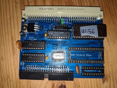
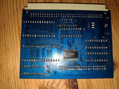
I have built alot of these interfaces, can you upload photo of both sides of the PCB.
Re: DIY QubIDE Parts list
Posted: Sun Oct 06, 2019 5:43 pm
by axeman
Hi,
Here are the photos

- Side1

- Side2
Re: DIY QubIDE Parts list
Posted: Sun Oct 06, 2019 8:25 pm
by martyn_hill
Hi Tom
Whilst there may be other problems (the programming of the GALs for one), it seems to me from your photo that the resistor array may be fitted back-to-front.
Pin 1 of the array is typically the 'common' pin and marked with the white 'dot', should be connected to Vcc and marked on the PCB adjacent to the ROM. If I read your photo properly, the white dot is on the left rather than the right (looking from the top-side.)
I may be completely wrong, of course - just a thought and easy enough to switch-around.
Good luck - I'll be assembling my own soon...
M.
Re: DIY QubIDE Parts list
Posted: Sun Oct 06, 2019 8:40 pm
by axeman
Well spotted.
Will try in the morning
Many thanks M.
Re: DIY QubIDE Parts list
Posted: Sun Oct 06, 2019 9:28 pm
by Derek_Stewart
Hi,
I think Martyn is correct, the resistor array is the wrong way around. Pin 1 on the resistor array is next to the Qubide eprom.
If you look closely on the PCB mask, Pin 1 is marked.
Re: DIY QubIDE Parts list
Posted: Mon Oct 07, 2019 9:21 am
by axeman
Thanks so far guys but after replacing and orienting the resistor array correctly still getting black and white lines?

- qubide_noboot