In my recent attempt to resurrect my QL I've been able to learn and fix it partially, but I still have some way to do, so just hope that someone with more experience and knowledge could help me a bit.
Here are the facts:
- Bought a non-working QL -> Did not even power up (No image on display, no power on led). Checked the IC35 -> 7805 Power regulator and found that was giving just 1V. Replaced. And replaced D25 and D26 and IC36 and IC37 with the coresponding 78L12 and 79L12 transistors.
- This fixed the supply problems and the QL was brought to life again, EUREKA! However, there was something strange (even for me that I wasn't used to the QL-color scheme...).
Someimes a picture is worth thousand words, so here it is:
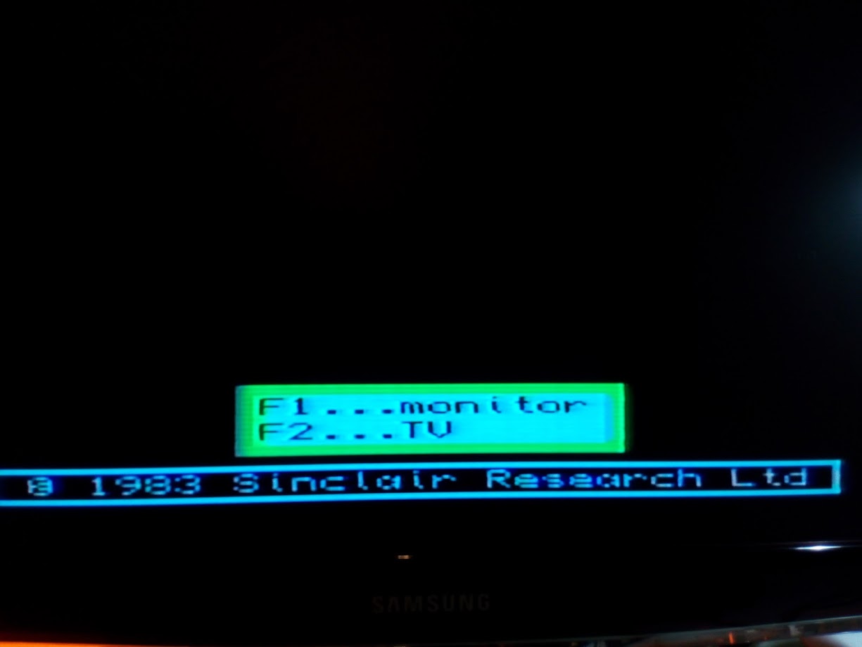
So, by some reason the red color is not present.
My first culprit was the MC1377P and the oscilloscope proved that my idea could not be wrong at all: I could see activity on pins 4 and 5 but not on pin 3.
So, I ordered a couple of ICs on Aliexpress and waited until they arrived.
Finally they arrived and yesterday did the IC swap...but the problem persists
Turned to check resistor R48 (measured 8,2Kohm) and C23 (the capacitor gave me around 40uF so replaced it by another 22 uF but that did not make any difference).
So, arrived to this point:
- The MC1377 is discarded as it's been replaced and it measures 12,01V on pin 14
- I noticed some activity readings on the osc on the left pad of R57, but checked continuity on all pads (R57<->R48<->C23<->IC pin 3) and was fine.
- I tried a desesperate attempt to gain some "red" color and tried to connect a bypass wire from R57 to pin3 of MC1377. This did not bring back the RED color where it should be, but in the opposite, the black color had a reddish tonality.
- Could it be that I'm assuming that the problem is related to R signal and may be other problem laying around? (perhaps chroma / luma?)
Thanks for any help in advance!