
I would have to look over the logic of the card again. You also have the small display - which could convey a lot more information than an LED - but the LED is good for a quick sanity check
New microdrive internal replacement
Re: New microdrive internal replacement
It stands to reason that you will only be reading or writing - never doing both at the same time - and I am guessing that the status LED is indicating the presence or not of the SD card?
I would have to look over the logic of the card again. You also have the small display - which could convey a lot more information than an LED - but the LED is good for a quick sanity check
I would have to look over the logic of the card again. You also have the small display - which could convey a lot more information than an LED - but the LED is good for a quick sanity check

Re: New microdrive internal replacement
No if I understood right. Status get activated as soon as you select the MDV where the replacement is (the cartridge is powered). It is useful to avoid damage in case you want to remove it when it is powered.
About Write and Read... I see lines for them and (it is just my supposition) for debugging purpose.
In my opinion... if Status led is on, I Don't care about W/R lines because I know the cartridge MUST not remove is SELECTED led is on. Perhaps, it could be nice to have just one activity LED (any activity read/write).
What could happen at same time, and I checked it out... is ACTIVED & (READ or WRITE) activity.
Exactly that is what I think.
In fact I have noticed that Cartridge get powered on as soon as screen get on, so... selected LED could be redundant. I will check it out in a couple of minutes.
Re: New microdrive internal replacement
I think a bi colour led - with common anode or cathode - that indicates one colour or another depending on whether reading or writing is taking place - it's nice to know which is happening - but my guess is they won't both be on simultaneously
Re: New microdrive internal replacement
I like it. Hum... very nice idea.
Now some updates... measuring the board and placing components to check out any issue to fit the case...
I saw... 2 leds on the case already ...
I am new on QL so... didn't saw it till now
I don't know for what is it till I try it again (not sure if I have time today).
And...
WARNING!!!!
Don't make my mistake. I hurt my QL case because I didn't remove the extra pins from my screen.
Also as you can see... with my QL case, the cartridge get too close if I use the microSD modele, that is another good reason to add the microSD footprint (already done).
In a while I will check those leds and for sure, one LED on the cartdrige could be removed.
Also thinking about to enlarge the cartridge a little more to get everything completally out from case edge (Screen, leds & mSD module).
Be aware with your QL case, I don't know if between QL versions cases could be different.
In any case, there is always the original design from Dr. Gusman.
Re: New microdrive internal replacement
I have uploaded a video explaining some things to consider and how nice it works.
https://youtu.be/8ONdMnC0Kfs
Next video is about what I am developing (modifications) from the original Dr. Gusman work.
https://youtu.be/pAIVefOURx0
Note: Verified, selected LED (first one) is "useless" for regular user. QL already has the same LED and functionality, so it can be removed (unless you need it for debugging hardware that you may be developing).
-
Derek_Stewart
- Font of All Knowledge
- Posts: 4038
- Joined: Mon Dec 20, 2010 11:40 am
- Location: Sunny Runcorn, Cheshire, UK
Re: New microdrive internal replacement
Hi,
Nice video, left a thumbs up.
Maybe the RP2040-Zero, with a smaller frontprint might help with the space problem.
Could the IDC cable connecting to the MDV connector be attached to the bottom of the PCB, rather than the top, saving bending the cable from the top of the PCB.
Nice video, left a thumbs up.
Maybe the RP2040-Zero, with a smaller frontprint might help with the space problem.
Could the IDC cable connecting to the MDV connector be attached to the bottom of the PCB, rather than the top, saving bending the cable from the top of the PCB.
Regards,
Derek
Derek
Re: New microdrive internal replacement
Hi, thanks. New video is uploading now with what I am changing on the board.
Is it not already RBP2040? (I don't know sub-versions). At any case, new videos tells what I think is a solution.Derek_Stewart wrote: ↑Mon Nov 20, 2023 6:33 pm Maybe the RP2040-Zero, with a smaller frontprint might help with the space problem.
That is what I though... ... till y tried it out somehow and I saw how it was pretty hard because to connect it to the board need to keep same pinout order and for that will be necessary to twist the cable (pin1 to pin1). Do you know what I mean?Derek_Stewart wrote: ↑Mon Nov 20, 2023 6:33 pm Could the IDC cable connecting to the MDV connector be attached to the bottom of the PCB, rather than the top, saving bending the cable from the top of the PCB.
Last edited by Popopo on Wed Nov 22, 2023 10:07 am, edited 1 time in total.
Re: New microdrive internal replacement
Hi all,
Here is another tip...
With the previous versions to the one I am designing now...
Be aware of soldering RBP under PCB (for MDV1), if you doesn't socked it... how are you going to programming it without options to push the button?
That's it.
No idea how RBP works... but I understood it now that I Was making some testing with previous versions.
Today I will send to make some prototypes of my own modification boards.
But I think the result is amazing (if it works).
Soon I will share the Gerbers files. And documented it with the changelog.
It is... just a beautiful and amazing device! and soooo cheap to make!
Re: New microdrive internal replacement
Hi! non Stop day
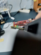
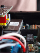
Here are some pictures to illustrate some points to be aware (at least in the ver 1.2 drive board, probably about ver 1.0 too).
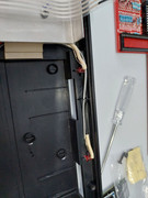
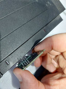
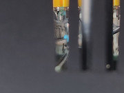
It is possible to use sockets for the bottom localization RBP2040, but... it get close to the Hermes/SuperHermes. So check it before to power on the QL, and could be safer to cut off the pins under the RBP2040. See photos.
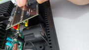
Next... as I said before... it is not possible to use (once socket-ed under board) to use it on MDV2 place, due to the Speaker. So before to solder, decide where you want it and set it up according with it:
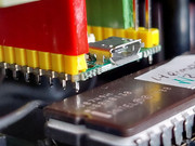
Last not the less, I detect an issue that it is about original version 1.0 and modified version 1.2 (at least I named it like that. PCBWay version is 1.0, GitHub version is 1.4).
The Edge socket get pushed down by the case rails (upper), so... no solution for it without mechanization of the Edge connector or removing rails (I don't like this one at all, because rails are there to lead the original MicroDrive cartridge).
See picture:
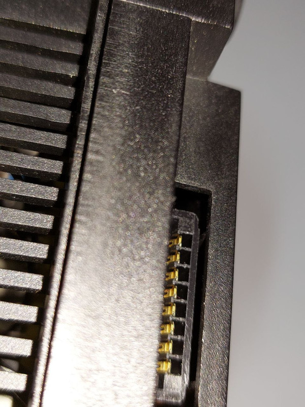
If you are going to do more than one board with it, and found same problems... please await some weeks till I get my own design of those boards and make them public. But my version (I call it 1.4) will not solve the EDGE connector issue (illustrated in last photo).
So... that is all with the main branch and modifications on it keeping retro compatibility. with previous versions
What next?
I will change a huge changes hoping to become improvements but it could take me more than 1 month due to need to recode the software too.
Future changes:
1. Change the EDGE connector for another one smaller. To solve the problem with the upper case rails (over EDGE connector). This way you can use the board in any place combined with original MicroDrive.
2. Removing all leds from cartridge
3. All info on the oLED Screen.
4. Option for using a larger screen than 0.49, for a wider format.
And Next?
1. Use a RBP Pico with Bluetooth or Wifi connection in order to allows upgrades without need to open the QL. (I will... try it, not promised land)
2. End of it, because already is a perfect replacement for any QL, at any place.
Here are some pictures to illustrate some points to be aware (at least in the ver 1.2 drive board, probably about ver 1.0 too).
It is possible to use sockets for the bottom localization RBP2040, but... it get close to the Hermes/SuperHermes. So check it before to power on the QL, and could be safer to cut off the pins under the RBP2040. See photos.
Next... as I said before... it is not possible to use (once socket-ed under board) to use it on MDV2 place, due to the Speaker. So before to solder, decide where you want it and set it up according with it:
Last not the less, I detect an issue that it is about original version 1.0 and modified version 1.2 (at least I named it like that. PCBWay version is 1.0, GitHub version is 1.4).
The Edge socket get pushed down by the case rails (upper), so... no solution for it without mechanization of the Edge connector or removing rails (I don't like this one at all, because rails are there to lead the original MicroDrive cartridge).
See picture:
If you are going to do more than one board with it, and found same problems... please await some weeks till I get my own design of those boards and make them public. But my version (I call it 1.4) will not solve the EDGE connector issue (illustrated in last photo).
So... that is all with the main branch and modifications on it keeping retro compatibility. with previous versions
What next?
I will change a huge changes hoping to become improvements
Future changes:
1. Change the EDGE connector for another one smaller. To solve the problem with the upper case rails (over EDGE connector). This way you can use the board in any place combined with original MicroDrive.
2. Removing all leds from cartridge
3. All info on the oLED Screen.
4. Option for using a larger screen than 0.49, for a wider format.
And Next?
1. Use a RBP Pico with Bluetooth or Wifi connection in order to allows upgrades without need to open the QL. (I will... try it, not promised land)
2. End of it, because already is a perfect replacement for any QL, at any place.
Re: New microdrive internal replacement
Hi
Great work by you and Gusman, I will order PCBs when you have tested after all the changes!
Regards
Chris
Great work by you and Gusman, I will order PCBs when you have tested after all the changes!
Regards
Chris